Delphi, the navel of the world

A spectacular path between steep mountains and rugged coastline leads us up there where the gods of the ancient world had positioned the center of the world or rather the navel of the Mediterranean world. Delphi is a spectacular archaeological site that clings tenaciously to the slopes of Mount Parnassus and opens onto a vast and fertile valley, cultivated with olive groves. The view is made even more spectacular by the proximity to the Gulf of Corinth, creating an exceptional situation in which the sea and the mountains meet just a short distance away.

The archaeological site of Delphi is a gem of the ancient Greek world, with its temples, or rather the remains of the thesauroi votives of the Greek cities, the theater, the stadium. Walking up the sacred road, one can perceive the millenary history of this place, where the priestess Pizia generated her oracles in the temple of Apollo, where countless numbers of the many pilgrims of the past can be read. Among the many, we still read gnōthi seautón, the “know yourself” of Socratic memory.

Travel tip: Take a relaxing break from the trip at the Camping Delphi, overlooking the olive groves and the sea, then visit the archaeological site at sunrise or sunset.

Delphi, the navel of the world, Greece

Volos, Koropi and the Pilio peninsula

We leave several friends at Meteora, but the trip will make us meet again. A last look at the beautiful stone mushrooms that overlook us and we leave for the sea, near Volos. We cross fields of wheat burned by the sun at the end of spring and we see countless huts of farmers and farmers on the hills. Finally we see the Gulf of Volos with its port and its white mantle of houses surrounding it. Quiet atmosphere. Think of the experience of TEM, the virtual alternative unit that was born as a Greek experiment to implement a system of exchange of knowledge and work similar to the time bank. The slopes of the Pilio were the refuge of the centaur and now defend themselves from the masses of tourists hiding small jewels like the beach of Mylopótamos or small villages like Koropi, where we stop one night to enjoy the slow and relaxed rhythms of the Greek villages.

Travel tip: Eat by the taverna and enjoy Greek salads, moussaka, pastrami cakes and many other typical Greek dishes

Volos, Koropi and the Pilio peninsula, Greece

How to design and develop a 3D printed multiplication tables learning tool

INTRODUCTION AND SCOPE

Multiplication tables are a challenge for kids to learn, but they could be turned into a game! This procedure aims to explain how to design and create a 3D printed multiplication tables learning tool (mandala) based upon the Montessori method. This is usually called the Montessori wheel or mandala of multiplication tables.

MATERIALS AND EQUIPMENT

3D Printer and PLA material (one color of choice), 1 meter long colored (possibly not the same color of the 3D printed part) wire.

PROCEDURE

  1. Download the stl file of the Montessori mandala (Hardware resources, link 2)
  2. 3D Print the Montessori mandala (Image 1)
  3. Tie the wire on the upper pin (position 12am), the other pins are numbered clockwise from 1 to 9
  4. While counting the multiplication tables (possible from 1 to 9), the wire must be turned around the corresponding pin (Image 2). For each sequence a different geometrical shape is created on the wheel. For example, by executing the sequence for the four multiplication table a star is created with the wire on the wheel (Image 2).

IMAGES

montessori wheel 3D printed
Image 1 – 3D printed Montessori wheel
montessori wheel example four multiplication table photo
Image 1 – 3D printed Montessori wheel example of four multiplication table

HARDWARE RESOURCES

  1. Used 3D printer: Sharebot NG.
  2. Stl file: 3D printed Montessori wheel mandala multiplication tables.stl
  3. G-code from stl file generated with Slic3r

SOFTWARE RESOURCES

None

CREDITS

None

DISCLAIMER

The project is provided in the spirit of open source and can be implemented, modified and shared according to CC BY-SA license (see footer). No liability is taken for any issues arising from the provided information.

CHANGELOG

  • 23/APR/2018 – New release

From Igoumenitsa to the Meteora monasteries

The ferry silts the calm sea when suddenly, after following the jagged coast of Albania and flanked the island of Corfu, it turns towards the bay of Igoumenitsa. A fresh morning, the ferry docks with a slight delay and immediately begins the journey. The road runs fast on steep hills, climbs up the sides of mountains covered with green pine forests and finally descends to perdifiato towards Ioannina. We are attracted by the quiet promenade along the lake and we are surprised by the mixed soul of this city where today’s European and Balkan tourists mix a distant memory of the Arab world and a more current Orthodox mysticism. To remind us of the smell of the streets of Ioannina, where Arab sweets, spices and silver handicrafts are still sold, as in a Middle Eastern souk. Overlooking an esplanade, which was the palace and still the tomb of Ali Pasha, the Ottoman ruler of Ioannina, where minarets and Orthodox churches coexist, in an architectural and cultural contrast that unexpectedly bring us closer to the eastern borders of Europe.

Still a few hours of travel and the natural spectacle of the Meteora monasteries, opens up before our eyes, leaving us speechless. The monks of the monastery of Varlaam look at us with detachment as we climb the stairs overhanging the monolithic rock formations, which explain to us that they have formed as the result of river erosion.

Travel suggestion: Camping Vrachos Kastraki, Meteora monasteries.

From Igoumenitsa to the Meteora monasteries, Greece

How to design an develop a low consumption music player based upon an arduino clone

INTRODUCTION AND SCOPE

Using an Atmega 328P chip without arduino board and with standalone power supply is a powerful, cheap, functional and low consumption solution. This procedure explains how to design and develop a low consumption music player based upon an arduino clone.

MATERIALS AND EQUIPMENT

Atmega 328P, 8Mhz Resonator, 10kOhm Resistor, DC/DC Step-up Converter with USB 5 Volt output, 3D printed Flexing battery case (1 or 2 battery slots) and/or Battery pack (e.g. 1/2 AA 1.2V or 1 Li-ion 3.7V), 8 Ohm speaker, Button switch, Wiring, Soldering.

PROCEDURE

  1. Setup the arduino clone (Hardware resources, link 1). In order to match the logic of the custom music player firmware (basically to have the music played at the proper frequency rate/speed), it is recommended to use a 8MHz resonator instead of the 16MHz resonator, with  the first option ensuring extra lower power consumption
  2. Using the Arduino IDE (Hardware resources, link 1), burn onto the arduino clone the music player firmware (Software resources, link 1). This includes a function to play melodies, 5 different melodies and a sleep function to lower consumption
  3. Setup the power supply for the arduino clone: one option is to create a 3D printed flexible battery case for a minimum of 1 AA battery or 2 AA batteries (Hardware resources, link 2); second option is to acquire 1 Li-ion 3.7V with wired battery case (this option is quicker to setup the power supply). This includes the DC/DC Step-up Converter with USB 5 Volt output for both battery options, with the second option ensuring lower power consumption (higher voltage conversion efficiency)
  4. Setup the arduino clone and the power supply on a custom board or a breadboard with at least 400 contacts (Image 1)
  5. Connect the 8 Ohm speaker to the arduino clone (digital pin 8) and to the power supply positive pole in series to a 100 Ohm resistor (Image 1)
  6. Connect the button switch to the arduino clone (digital pin 4) and to the power supply poles as applicable for the specific switch (Image 1)
  7. Power the circuit with the batteries. The first short melody will automatically play
  8. Push the button switch to play the next melody. Wait until the playing melody finishes before pushing the button switch for the following melody
  9. Enjoy and figure out how to add new melodies. You are encouraged to share under comments below your musical successes!

IMAGES

Music player hardware with arduino clone, speaker and battery pack
Image 1 – Music player hardware with arduino clone, speaker and battery pack

HARDWARE RESOURCES

  1. How to design and develop a simple, small sized and fully functional arduino clone
  2. How to design and develop a power supply for an arduino clone

SOFTWARE RESOURCES

  1. Music player firmware v4 (.ino file)

CREDITS

  1.  Play a Melody using the tone() function (arduino)
  2. atmega168 Melody Module (fritzing)

DISCLAIMER

The project is provided in the spirit of open source and can be implemented, modified and shared according to CC BY-SA license (see footer). No liability is taken for any issues arising from the provided information.

CHANGELOG

  • 05/SEP/2017 – New release

How to design a 3D printed lamp with a lithographic 3D printed photo

INTRODUCTION AND SCOPE

Table or bedsides lamps are common objects in modern homes not only to light up but also to decorate. This procedure aims to explain how to design a 3D printed table or bedside lamp with a lithographic 3D printed photo, that creates a very original and personal look.

MATERIALS AND EQUIPMENT

3D Printer and PLA material (black for the case and white for the 3D printed photo), 1 white or coloured LED, 1 battery.

PROCEDURE

  1. Take a picture and if not already black&white, make it so with any picture formatting program e.g. Microsoft Powerpoint (Picture Tools – Format – Color – Black and White Recolor). Save it in JPEG format.
  2. Reduce at minimum the size of the picture with any picture formatting program e.g. Microsoft Office Picture Manager (Edit Pictures – Compress pictures – Web Pages – Save)
  3. Download Processing and run it. Download the Model Builder library, unzip the library file, and copy the folder into Processing’s “libraries” folder. Once this is done restart Processing. Download the Lithograph3DPrint Processing sketch.
  4. Open the folder Lithograph3DPrint. Copy any grayscale images (preferably Black and White per step1, to optimize processing time) you want to convert into this folder.
  5. To run the sketch, replace the part in quotes in following line: String name = “your_file_name_here.jpg” with the name of your grayscale image. Define in the sketch the X and Z dimensions (X drives the size of the image and the time needed to print, while Z drives the print resolution and opacity, depending on the material selected):
    1. float widthDim = 150;//width dimension (in mm)
    2. float zDim = 1.00;//max vertical displacement (in mm)
    3. float thickness = 0.40;//base thickness (in mm)
  6. Run the sketch, after a minute or two Processing will tell you that it is writing an STL file and that it is finished. The resulting file will be located in the sketch’s folder named “NAME_OF_ORIGINAL_FILE.stl”
  7. Move the newly created stl file in the appropriate stl folder and open it with netfabb. Analyze the file and if errors are found, correct them (Repair tool – Execute – Apply – Save)
  8. Open the repaired stl file with Repetier Host and create the G code for the appropriate material (White PLA successfully tested) and the appropriate slice settings (Medium quality is recommended). The slicing process can take minutes if the image is large in size
  9. 3D Print the lithograph and the lamp case (Hardware resources, link 2); both dimensions matching the 150mm square shape of the 3D printed photo (Image 1)
  10. Backlight it with custom LEDs (Hardware resources, link 4 and 5) or bulb light according to aesthetic, safety and feasibility (Image 1).

IMAGES

3D printed lamp with a lithographic 3D printed photo
Image 1 – 3D printed lamp with a lithographic 3D printed photo

HARDWARE RESOURCES

  1. Used 3D printer: Sharebot NG.
  2. Stl file (for the lamp case): 3D printed lamp case.stl
  3. G-code from stl file generated with Slic3r
  4. Wiring up LEDs
  5. LED resistor calculator

SOFTWARE RESOURCES

  1. Processing
  2. Model Builder library
  3. Lithograph3DPrint

CREDITS

  1. Github: amandaghassaei
  2. Amandaghassaei.com

DISCLAIMER

The project is provided in the spirit of open source and can be implemented, modified and shared according to CC BY-SA license (see footer). No liability is taken for any issues arising from the provided information.

CHANGELOG

  • 18/AUG/2017 – New release

How to design and develop a power supply for an arduino clone

INTRODUCTION AND SCOPE

An Atmega 328P without arduino board can achieve the same capabilities of the arduino board, using the same arduino IDE programming and coding environment. Using an Atmega 328P chip without arduino board is powerful, cheap and functional. For a fully standalone setup, this requires a dedicated power supply. This procedure explains how to design and develop a power supply for an arduino clone.

MATERIALS AND EQUIPMENT

DC/DC Step-up Converter with USB 5 Volt output, 3D printed Flexing battery case (1 or 2 battery slots), 1 or 2 AA batteries, Wiring, Soldering.

PROCEDURE

  1. Wire and solder the USB power and ground pins on the DC/DC Step-up Converter with USB 5 Volt output (Hardware resources, link 1) (Image 2). The recommended DC/DC Step-up Converter can take as an input a voltage between 0.9 and 5 Volt and gives an output of 5 Volt with 500mA (when connecting 2 AA batteries) or 200mA (when connecting 1 AA battery)
  2. Wire and solder the battery power and ground pins on the DC/DC Step-up Converter with USB 5 Volt output (Hardware resources, link 1) (Image 1).
  3. 3D print the flexible battery case according to the recommendations at the provided resource (Hardware resources, link 2). The suggestion is to print single battery cases (1 or 2 depending on requirement)
  4. Wire the flexible battery case(s) in series to the battery power and ground pins on the DC/DC Step-up Converter with USB 5 Volt output (Image 1)
  5. Insert the charged AA battery into the flexible battery case(s)
  6. Provide power supply from the USB power and ground outputs of the DC/DC Step-up Converter to the standalone Atmega 328P (Hardware resources, link 3)

IMAGES

Power supply for an arduino clone
Image 1 – Power supply for an arduino clone
USB type A pinout
Image 2 – USB type A pinout

HARDWARE RESOURCES

  1. DC/DC Step-up Converter with USB 5 Volt output
  2. Flexing battery case
  3. How to design and develop a simple, small sized and fully functional arduino clone

SOFTWARE RESOURCES

N/A

CREDITS

  1. Arduino to Breadboard

DISCLAIMER

The project is provided in the spirit of open source and can be implemented, modified and shared according to CC BY-SA license (see footer). No liability is taken for any issues arising from the provided information.

CHANGELOG

  • 13/FEB/2017 – New release

How to design and develop a simple, small sized and fully functional arduino clone

INTRODUCTION AND SCOPE

An Atmega 328P without arduino board can achieve the same capabilities of the arduino board, using the same arduino IDE programming and coding environment. Using an Atmega 328P chip without arduino board is powerful, cheap and functional. This procedure explains how to design and develop a simple, small sized and fully functional arduino clone.

MATERIALS AND EQUIPMENT

Arduino UNO, Atmega 328P, 10kOhm resistor, 16Mhz resonator.

PROCEDURE

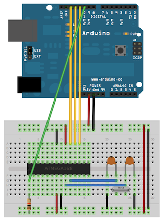
  1. Before wiring the two boards, familiarize with the pin configurations of the Atmega 328P on page 3 of the datasheet (Hardware resources, link 1)
  2. Switch on the PC, open the Arduino IDE and connect the Arduino Uno board with USB connection. Select the board and serial port corresponding to the Arduino Uno board in the Arduino IDE>Tools. These are standard steps for Arduino board USB connection (Hardware resources, link 2)
  3. Upload the ArduinoISP sketch onto your Arduino Uno board from the Arduino IDE>File
  4. Wire up the Arduino Uno board and the Atmega 328P on a breadboard (Image 1). The two 18 to 22 picofarad (ceramic) capacitors are optional
  5. Select “Arduino Duemilanove or Nano w/ ATmega328” from the Arduino IDE>Tools >Board menu
  6. Select “Arduino as ISP” from the Arduino IDE>Tools >Programmer
  7. Run from the Arduino IDE>Tools >Burn Bootloader
  8. Once the bootloader is burnt on the Atmega 328P, switch off the Arduino Uno board by disconnecting the USB cable
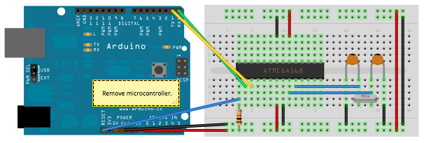
  9. Remove the microcontroller of the Arduino Uno board
  10. Wire up the Arduino Uno board and the Atmega 328P on a breadboard (Image 2). The two 18 to 22 picofarad (ceramic) capacitors are optional
  11. Switch on the Arduino Uno board by re-connecting the USB cable
  12. Select “Arduino Duemilanove or Nano w/ ATmega328” from the Arduino IDE>Tools >Board menu
  13. Write and upload any program with the Arduino IDE upload command.
  14. Unwire the Arduino Uno board
  15. Provide power supply to the standalone Atmega 328P (Hardware resources, link 3)

IMAGES

Using an Arduino board to burn the bootloader onto an ATmega on a breadboard
Image 1 – Arduino board as an in-system program (ISP)
Uploading sketches to an Atmega 328P on a breadboard
Image 2 – Arduino board as sketch uploader to an Atmega 328P

HARDWARE RESOURCES

  1. Atmega 328P Datasheet
  2. Arduino Uno
  3. How to design and develop a power supply for an arduino clone

SOFTWARE RESOURCES

  1. Arduino IDE

CREDITS

  1. Arduino to Breadboard

DISCLAIMER

The project is provided in the spirit of open source and can be implemented, modified and shared according to CC BY-SA license (see footer). No liability is taken for any issues arising from the provided information.

CHANGELOG

  • 24/JAN/2017 – New release

Biomedical engineering notes – Thermo fluid dynamics

Program
Heat conduction. The heat diffusion equation. Boundary and initial conditions. Steady-state and transient conduction. The finite difference method applied to the heat equation. Forced convection. The velocity and thermal boundary layers. The convection coefficient. Laminar and turbulent flow. Dimensionless groups of forced convection. Heat transfer correlations in external and internal flows. Free convection: physical consideration and governing equations. The dimensionless groups of free convection. The effects of turbulence. Heat transfer correlations. Heat exchangers. Heat exchangers types. Design and performance calculations. Fundamentals of heat transfer in boiling and condensation. Heat transfer by radiation. Processes and properties. Radiation exchange between surfaces. Radiation exchange with participating media.

Notes

Source
Biomedical engineering notes

Biomedical engineering notes – Technologies for sensors and instrumentation

Program
Sensors for biomedical instrumentation: classification. Operating principles: photoelectric, thermoresistive, thermoelectric, piezoelectric, pyroelectric, piezoresistive, magnetic, induced by radiation, adsorption and absorption of chemical species. Technology: semiconductors, ceramics, polymer films, optical fibers. Structures: impedance, semiconductor, acoustic waves, calorimetric sensors, electrochemical cells, in the optical waveguide. Applications in medicine and biology of electromagnetic radiation sensors, thermal, mechanical, chemical. Technologies of electronic instrumentation. Structure of a measuring system. Interfacing with the sensor, signal conditioning, filtering and signal processing. Analog/Digital conversion. Microprocessor-based systems for biomedical instrumentation. Hardware architectures (microcontrollers, DSP, PC-based systems), software (embedded systems, real-time operating systems, virtual instrumentation) and networking (digital communication techniques: field bus, classification and characteristics of the protocols, telemetry).
Characteristics, and principles of measurement of biomedical sensors. Semiconductors technologies. Sensors of force, pressure, motion, acceleration, temperature, humidity, gas concentration, EM radiation. Biomedical optics (photodiodes, LED, CCD, CMOS). Piezoelectric, pyroelectric and FET electrochemical sensors. Fiber optics sensors. Conditioning of sensors. Imaging systems for diagnosis (endoscopy, computed radiography, computed tomography, magnetic resonance imaging, nuclear imaging, medical ultrasonography). Equipment for hemodynamic and respiratory monitoring in anaesthesia and critical care medicine. Clinical laboratory measurements (spectrometric instruments, electrochemical analysis, electrophoresis). Microscopy. Surgical and therapeutic equipment.

Notes

Source
Biomedical engineering notes

This site uses cookies. If you consent, accept this message. For more options, read the Privacy Policy

The cookie settings on this website are set to "allow cookies" to give you the best browsing experience possible. If you continue to use this website without changing your cookie settings or you click "Accept" below then you are consenting to this.

Close