How to design an develop a low consumption music player based upon an arduino clone

INTRODUCTION AND SCOPE

Using an Atmega 328P chip without arduino board and with standalone power supply is a powerful, cheap, functional and low consumption solution. This procedure explains how to design and develop a low consumption music player based upon an arduino clone.

MATERIALS AND EQUIPMENT

Atmega 328P, 8Mhz Resonator, 10kOhm Resistor, DC/DC Step-up Converter with USB 5 Volt output, 3D printed Flexing battery case (1 or 2 battery slots) and/or Battery pack (e.g. 1/2 AA 1.2V or 1 Li-ion 3.7V), 8 Ohm speaker, Button switch, Wiring, Soldering.

PROCEDURE

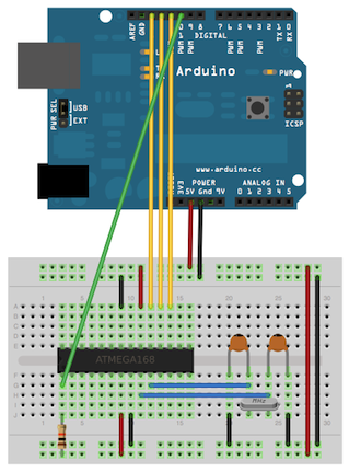
  1. Setup the arduino clone (Hardware resources, link 1). In order to match the logic of the custom music player firmware (basically to have the music played at the proper frequency rate/speed), it is recommended to use a 8MHz resonator instead of the 16MHz resonator, with  the first option ensuring extra lower power consumption
  2. Using the Arduino IDE (Hardware resources, link 1), burn onto the arduino clone the music player firmware (Software resources, link 1). This includes a function to play melodies, 5 different melodies and a sleep function to lower consumption
  3. Setup the power supply for the arduino clone: one option is to create a 3D printed flexible battery case for a minimum of 1 AA battery or 2 AA batteries (Hardware resources, link 2); second option is to acquire 1 Li-ion 3.7V with wired battery case (this option is quicker to setup the power supply). This includes the DC/DC Step-up Converter with USB 5 Volt output for both battery options, with the second option ensuring lower power consumption (higher voltage conversion efficiency)
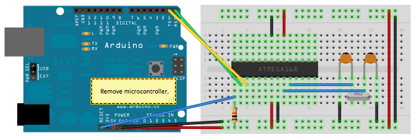
  4. Setup the arduino clone and the power supply on a custom board or a breadboard with at least 400 contacts (Image 1)
  5. Connect the 8 Ohm speaker to the arduino clone (digital pin 8) and to the power supply positive pole in series to a 100 Ohm resistor (Image 1)
  6. Connect the button switch to the arduino clone (digital pin 4) and to the power supply poles as applicable for the specific switch (Image 1)
  7. Power the circuit with the batteries. The first short melody will automatically play
  8. Push the button switch to play the next melody. Wait until the playing melody finishes before pushing the button switch for the following melody
  9. Enjoy and figure out how to add new melodies. You are encouraged to share under comments below your musical successes!

IMAGES

Music player hardware with arduino clone, speaker and battery pack
Image 1 – Music player hardware with arduino clone, speaker and battery pack

HARDWARE RESOURCES

  1. How to design and develop a simple, small sized and fully functional arduino clone
  2. How to design and develop a power supply for an arduino clone

SOFTWARE RESOURCES

  1. Music player firmware v4 (.ino file)

CREDITS

  1.  Play a Melody using the tone() function (arduino)
  2. atmega168 Melody Module (fritzing)

DISCLAIMER

The project is provided in the spirit of open source and can be implemented, modified and shared according to CC BY-SA license (see footer). No liability is taken for any issues arising from the provided information.

CHANGELOG

  • 05/SEP/2017 – New release

How to design and develop a power supply for an arduino clone

INTRODUCTION AND SCOPE

An Atmega 328P without arduino board can achieve the same capabilities of the arduino board, using the same arduino IDE programming and coding environment. Using an Atmega 328P chip without arduino board is powerful, cheap and functional. For a fully standalone setup, this requires a dedicated power supply. This procedure explains how to design and develop a power supply for an arduino clone.

MATERIALS AND EQUIPMENT

DC/DC Step-up Converter with USB 5 Volt output, 3D printed Flexing battery case (1 or 2 battery slots), 1 or 2 AA batteries, Wiring, Soldering.

PROCEDURE

  1. Wire and solder the USB power and ground pins on the DC/DC Step-up Converter with USB 5 Volt output (Hardware resources, link 1) (Image 2). The recommended DC/DC Step-up Converter can take as an input a voltage between 0.9 and 5 Volt and gives an output of 5 Volt with 500mA (when connecting 2 AA batteries) or 200mA (when connecting 1 AA battery)
  2. Wire and solder the battery power and ground pins on the DC/DC Step-up Converter with USB 5 Volt output (Hardware resources, link 1) (Image 1).
  3. 3D print the flexible battery case according to the recommendations at the provided resource (Hardware resources, link 2). The suggestion is to print single battery cases (1 or 2 depending on requirement)
  4. Wire the flexible battery case(s) in series to the battery power and ground pins on the DC/DC Step-up Converter with USB 5 Volt output (Image 1)
  5. Insert the charged AA battery into the flexible battery case(s)
  6. Provide power supply from the USB power and ground outputs of the DC/DC Step-up Converter to the standalone Atmega 328P (Hardware resources, link 3)

IMAGES

Power supply for an arduino clone
Image 1 – Power supply for an arduino clone
USB type A pinout
Image 2 – USB type A pinout

HARDWARE RESOURCES

  1. DC/DC Step-up Converter with USB 5 Volt output
  2. Flexing battery case
  3. How to design and develop a simple, small sized and fully functional arduino clone

SOFTWARE RESOURCES

N/A

CREDITS

  1. Arduino to Breadboard

DISCLAIMER

The project is provided in the spirit of open source and can be implemented, modified and shared according to CC BY-SA license (see footer). No liability is taken for any issues arising from the provided information.

CHANGELOG

  • 13/FEB/2017 – New release

How to design and develop a simple, small sized and fully functional arduino clone

INTRODUCTION AND SCOPE

An Atmega 328P without arduino board can achieve the same capabilities of the arduino board, using the same arduino IDE programming and coding environment. Using an Atmega 328P chip without arduino board is powerful, cheap and functional. This procedure explains how to design and develop a simple, small sized and fully functional arduino clone.

MATERIALS AND EQUIPMENT

Arduino UNO, Atmega 328P, 10kOhm resistor, 16Mhz resonator.

PROCEDURE

  1. Before wiring the two boards, familiarize with the pin configurations of the Atmega 328P on page 3 of the datasheet (Hardware resources, link 1)
  2. Switch on the PC, open the Arduino IDE and connect the Arduino Uno board with USB connection. Select the board and serial port corresponding to the Arduino Uno board in the Arduino IDE>Tools. These are standard steps for Arduino board USB connection (Hardware resources, link 2)
  3. Upload the ArduinoISP sketch onto your Arduino Uno board from the Arduino IDE>File
  4. Wire up the Arduino Uno board and the Atmega 328P on a breadboard (Image 1). The two 18 to 22 picofarad (ceramic) capacitors are optional
  5. Select “Arduino Duemilanove or Nano w/ ATmega328” from the Arduino IDE>Tools >Board menu
  6. Select “Arduino as ISP” from the Arduino IDE>Tools >Programmer
  7. Run from the Arduino IDE>Tools >Burn Bootloader
  8. Once the bootloader is burnt on the Atmega 328P, switch off the Arduino Uno board by disconnecting the USB cable
  9. Remove the microcontroller of the Arduino Uno board
  10. Wire up the Arduino Uno board and the Atmega 328P on a breadboard (Image 2). The two 18 to 22 picofarad (ceramic) capacitors are optional
  11. Switch on the Arduino Uno board by re-connecting the USB cable
  12. Select “Arduino Duemilanove or Nano w/ ATmega328” from the Arduino IDE>Tools >Board menu
  13. Write and upload any program with the Arduino IDE upload command.
  14. Unwire the Arduino Uno board
  15. Provide power supply to the standalone Atmega 328P (Hardware resources, link 3)

IMAGES

Using an Arduino board to burn the bootloader onto an ATmega on a breadboard
Image 1 – Arduino board as an in-system program (ISP)
Uploading sketches to an Atmega 328P on a breadboard
Image 2 – Arduino board as sketch uploader to an Atmega 328P

HARDWARE RESOURCES

  1. Atmega 328P Datasheet
  2. Arduino Uno
  3. How to design and develop a power supply for an arduino clone

SOFTWARE RESOURCES

  1. Arduino IDE

CREDITS

  1. Arduino to Breadboard

DISCLAIMER

The project is provided in the spirit of open source and can be implemented, modified and shared according to CC BY-SA license (see footer). No liability is taken for any issues arising from the provided information.

CHANGELOG

  • 24/JAN/2017 – New release

How to solve USB connection issues between computer and Rumba Taurino board

INTRODUCTION AND SCOPE

USB connection is an important feature to ensure the rumba taurino board remains operative. Unfortunately, problems can frequently arise. This procedure aims to explain how to solve USB connection issues between computer and Rumba Taurino board.

MATERIALS AND EQUIPMENT

Rumba taurino board, USB cable, Two-pins bridge.

PROCEDURE

  1. Switch on the computer (defined PC below). 3D printer or similar (defined device below) must be off.
  2. Under PC Device Manager (link: Start> Run> Driver) check if there are RUMBA TAURINO BOARD devices installed but not recognized (unknown). If there are unknown devices, remove them.
  3. With device off, identify the two pins highlighted in red (see Images sections). Short the two pins to switch to DFU mode (Device Firmware Update). More details on DFU mode can be found at the link provided under credits (link 3).
  4. Connect the USB cable to the PC and then to the device.
  5. Switch on the device.
  6. Wait for 10 seconds and then remove the short on the two pins (avoid making short-circuit with other pins). The LED of the serial communication (TX and RX) start blinking.
  7. PC detects new hardware and tries to install the driver. This automatic task should give a system error and fail to install any driver.
  8. Download the DFU programmer and the drivers for the USB connection of the Rumba Taurino board that can be found at the link provided under credits (link 1). Save it on PC and unzip it. This is the path of the driver and DFU programmer required in step 9 and 10.
  9. Open the tool for manual installation of drivers (link: Start> Run> hdwwiz). Select the option install from list, select show all devices, disk driver and insert the path where the drivers for the USB connection of the Rumba Taurino board are saved on the PC. From the list select ATmega16U2 to install the driver for the USB connection of the Rumba Taurino board.
  10. Run the DFU programmer to flash the USB port. If a message on memory error check appears, click a keyboard button to flash the port.
  11. If needed and if not already available on the PC, install the driver for Rumba Taurino board (not the USB driver installed in step 9!), that can be downloaded at the link provided under credits (link 2).
  12. Switch off the device and switch on again to verify that it is now recognized by the PC and a USB port is assigned. Under devices the Rumba Taurino board icon appears.

IMAGES

Rumba Taurino two pins to short

HARDWARE RESOURCES

See Credits.

SOFTWARE RESOURCES

See Credits.

CREDITS

  1. Rumba Taurino Board PC USB connection (github)
  2. RUMBA_TAURINO_DriverSetup (reprap)
  3. DFU Mode (arduino)

DISCLAIMER

The project is provided in the spirit of open source and can be implemented, modified and shared according to CC BY-SA license (see footer). No liability is taken for any issues arising from the provided information.

CHANGELOG

  • 07/JUN/2015 – New release
  • 16/FEB/2016 – Verbiage improved in step 2, Step 8 added, Description improved in step 9-10-11, Resource references improved with numbering
  • 05/OCT/2016 – Project structure improved with sections: Introduction and scope, Materials and Equipment, Procedure, Hardware resources, Software resources, Credits and Disclaimer.

Launching open source projects

This article launches a series of open source hardware and software projects that will be shared in the next future.

According to opensource.com, open hardware or open source hardware refers to the design specifications of a physical object which are licensed in such a way that said object can be studied, modified, created, and distributed by anyone. Open hardware is a set of design principles and legal practices, not a specific type of object. The term can therefore refer to any number of objects—like automobiles, chairs, computers, robots, or even houses.

Like open source software, the source code for open hardware (schematics, blueprints, logic designs, CAD drawings, etc) is available for modification or enhancement by anyone under permissive licenses. Users with access to the tools that can read and manipulate these source files can update and improve the code that underlies the physical device. They can add features or fix bugs in the software. The license governing the reproduction of open hardware must allow modification and distribution of those design files in a way that allows others to easily obtain them. This makes possible and even encourages studying, troubleshooting, modifying, and improving open hardware.

Open source hardware and software

This site uses cookies. If you consent, accept this message. For more options, read the Privacy Policy

The cookie settings on this website are set to "allow cookies" to give you the best browsing experience possible. If you continue to use this website without changing your cookie settings or you click "Accept" below then you are consenting to this.

Close