Multiplication tables are a challenge for kids to learn, but they could be turned into a game! This procedure aims to explain how to design and create a 3D printed multiplication tables learning tool (mandala) based upon the Montessori method. This is usually called the Montessori wheel or mandala of multiplication tables.
MATERIALS AND EQUIPMENT
3D Printer and PLA material (one color of choice), 1 meter long colored (possibly not the same color of the 3D printed part) wire.
PROCEDURE
Download the stl file of the Montessori mandala (Hardware resources, link 2)
3D Print the Montessori mandala (Image 1)
Tie the wire on the upper pin (position 12am), the other pins are numbered clockwise from 1 to 9
While counting the multiplication tables (possible from 1 to 9), the wire must be turned around the corresponding pin (Image 2). For each sequence a different geometrical shape is created on the wheel. For example, by executing the sequence for the four multiplication table a star is created with the wire on the wheel (Image 2).
IMAGES
Image 1 – 3D printed Montessori wheel
Image 1 – 3D printed Montessori wheel example of four multiplication table
The project is provided in the spirit of open source and can be implemented, modified and shared according to CC BY-SA license (see footer). No liability is taken for any issues arising from the provided information.
Using an Atmega 328P chip without arduino board and with standalone power supply is a powerful, cheap, functional and low consumption solution. This procedure explains how to design and develop a low consumption music player based upon an arduino clone.
MATERIALS AND EQUIPMENT
Atmega 328P, 8Mhz Resonator, 10kOhm Resistor, DC/DC Step-up Converter with USB 5 Volt output, 3D printed Flexing battery case (1 or 2 battery slots) and/or Battery pack (e.g. 1/2 AA 1.2V or 1 Li-ion 3.7V), 8 Ohm speaker, Button switch, Wiring, Soldering.
PROCEDURE
Setup the arduino clone (Hardware resources, link 1). In order to match the logic of the custom music player firmware (basically to have the music played at the proper frequency rate/speed), it is recommended to use a 8MHz resonator instead of the 16MHz resonator, with the first option ensuring extra lower power consumption
Using the Arduino IDE (Hardware resources, link 1), burn onto the arduino clone the music player firmware (Software resources, link 1). This includes a function to play melodies, 5 different melodies and a sleep function to lower consumption
Setup the power supply for the arduino clone: one option is to create a 3D printed flexible battery case for a minimum of 1 AA battery or 2 AA batteries (Hardware resources, link 2); second option is to acquire 1 Li-ion 3.7V with wired battery case (this option is quicker to setup the power supply). This includes the DC/DC Step-up Converter with USB 5 Volt output for both battery options, with the second option ensuring lower power consumption (higher voltage conversion efficiency)
Setup the arduino clone and the power supply on a custom board or a breadboard with at least 400 contacts (Image 1)
Connect the 8 Ohm speaker to the arduino clone (digital pin 8) and to the power supply positive pole in series to a 100 Ohm resistor (Image 1)
Connect the button switch to the arduino clone (digital pin 4) and to the power supply poles as applicable for the specific switch (Image 1)
Power the circuit with the batteries. The first short melody will automatically play
Push the button switch to play the next melody. Wait until the playing melody finishes before pushing the button switch for the following melody
Enjoy and figure out how to add new melodies. You are encouraged to share under comments below your musical successes!
IMAGES
Image 1 – Music player hardware with arduino clone, speaker and battery pack
The project is provided in the spirit of open source and can be implemented, modified and shared according to CC BY-SA license (see footer). No liability is taken for any issues arising from the provided information.
Table or bedsides lamps are common objects in modern homes not only to light up but also to decorate. This procedure aims to explain how to design a 3D printed table or bedside lamp with a lithographic 3D printed photo, that creates a very original and personal look.
MATERIALS AND EQUIPMENT
3D Printer and PLA material (black for the case and white for the 3D printed photo), 1 white or coloured LED, 1 battery.
PROCEDURE
Take a picture and if not already black&white, make it so with any picture formatting program e.g. Microsoft Powerpoint (Picture Tools – Format – Color – Black and White Recolor). Save it in JPEG format.
Reduce at minimum the size of the picture with any picture formatting program e.g. Microsoft Office Picture Manager (Edit Pictures – Compress pictures – Web Pages – Save)
Open the folder Lithograph3DPrint. Copy any grayscale images (preferably Black and White per step1, to optimize processing time) you want to convert into this folder.
To run the sketch, replace the part in quotes in following line: String name = “your_file_name_here.jpg” with the name of your grayscale image. Define in the sketch the X and Z dimensions (X drives the size of the image and the time needed to print, while Z drives the print resolution and opacity, depending on the material selected):
float widthDim = 150;//width dimension (in mm)
float zDim = 1.00;//max vertical displacement (in mm)
float thickness = 0.40;//base thickness (in mm)
Run the sketch, after a minute or two Processing will tell you that it is writing an STL file and that it is finished. The resulting file will be located in the sketch’s folder named “NAME_OF_ORIGINAL_FILE.stl”
Move the newly created stl file in the appropriate stl folder and open it with netfabb. Analyze the file and if errors are found, correct them (Repair tool – Execute – Apply – Save)
Open the repaired stl file with Repetier Host and create the G code for the appropriate material (White PLA successfully tested) and the appropriate slice settings (Medium quality is recommended). The slicing process can take minutes if the image is large in size
3D Print the lithograph and the lamp case (Hardware resources, link 2); both dimensions matching the 150mm square shape of the 3D printed photo (Image 1)
Backlight it with custom LEDs (Hardware resources, link 4 and 5) or bulb light according to aesthetic, safety and feasibility (Image 1).
IMAGES
Image 1 – 3D printed lamp with a lithographic 3D printed photo
The project is provided in the spirit of open source and can be implemented, modified and shared according to CC BY-SA license (see footer). No liability is taken for any issues arising from the provided information.
An Atmega 328P without arduino board can achieve the same capabilities of the arduino board, using the same arduino IDE programming and coding environment. Using an Atmega 328P chip without arduino board is powerful, cheap and functional. For a fully standalone setup, this requires a dedicated power supply. This procedure explains how to design and develop a power supply for an arduino clone.
MATERIALS AND EQUIPMENT
DC/DC Step-up Converter with USB 5 Volt output, 3D printed Flexing battery case (1 or 2 battery slots), 1 or 2 AA batteries, Wiring, Soldering.
PROCEDURE
Wire and solder the USB power and ground pins on the DC/DC Step-up Converter with USB 5 Volt output (Hardware resources, link 1) (Image 2). The recommended DC/DC Step-up Converter can take as an input a voltage between 0.9 and 5 Volt and gives an output of 5 Volt with 500mA (when connecting 2 AA batteries) or 200mA (when connecting 1 AA battery)
Wire and solder the battery power and ground pins on the DC/DC Step-up Converter with USB 5 Volt output (Hardware resources, link 1) (Image 1).
3D print the flexible battery case according to the recommendations at the provided resource (Hardware resources, link 2). The suggestion is to print single battery cases (1 or 2 depending on requirement)
Wire the flexible battery case(s) in series to the battery power and ground pins on the DC/DC Step-up Converter with USB 5 Volt output (Image 1)
Insert the charged AA battery into the flexible battery case(s)
Provide power supply from the USB power and ground outputs of the DC/DC Step-up Converter to the standalone Atmega 328P (Hardware resources, link 3)
The project is provided in the spirit of open source and can be implemented, modified and shared according to CC BY-SA license (see footer). No liability is taken for any issues arising from the provided information.
An Atmega 328P without arduino board can achieve the same capabilities of the arduino board, using the same arduino IDE programming and coding environment. Using an Atmega 328P chip without arduino board is powerful, cheap and functional. This procedure explains how to design and develop a simple, small sized and fully functional arduino clone.
Before wiring the two boards, familiarize with the pin configurations of the Atmega 328P on page 3 of the datasheet (Hardware resources, link 1)
Switch on the PC, open the Arduino IDE and connect the Arduino Uno board with USB connection. Select the board and serial port corresponding to the Arduino Uno board in the Arduino IDE>Tools. These are standard steps for Arduino board USB connection (Hardware resources, link 2)
Upload the ArduinoISP sketch onto your Arduino Uno board from the Arduino IDE>File
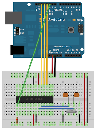
Wire up the Arduino Uno board and the Atmega 328P on a breadboard (Image 1). The two 18 to 22 picofarad (ceramic) capacitors are optional
Select “Arduino Duemilanove or Nano w/ ATmega328” from the Arduino IDE>Tools >Board menu
Select “Arduino as ISP” from the Arduino IDE>Tools >Programmer
Run from the Arduino IDE>Tools >Burn Bootloader
Once the bootloader is burnt on the Atmega 328P, switch off the Arduino Uno board by disconnecting the USB cable
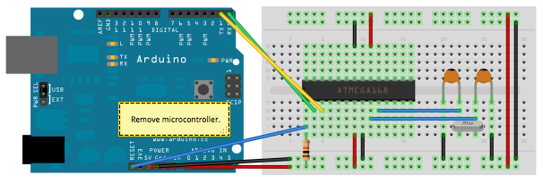
Remove the microcontroller of the Arduino Uno board
Wire up the Arduino Uno board and the Atmega 328P on a breadboard (Image 2). The two 18 to 22 picofarad (ceramic) capacitors are optional
Switch on the Arduino Uno board by re-connecting the USB cable
Select “Arduino Duemilanove or Nano w/ ATmega328” from the Arduino IDE>Tools >Board menu
Write and upload any program with the Arduino IDE upload command.
Unwire the Arduino Uno board
Provide power supply to the standalone Atmega 328P (Hardware resources, link 3)
IMAGES
Image 1 – Arduino board as an in-system program (ISP)
Image 2 – Arduino board as sketch uploader to an Atmega 328P
The project is provided in the spirit of open source and can be implemented, modified and shared according to CC BY-SA license (see footer). No liability is taken for any issues arising from the provided information.
USB connection is an important feature to ensure the rumba taurino board remains operative. Unfortunately, problems can frequently arise. This procedure aims to explain how to solve USB connection issues between computer and Rumba Taurino board.
MATERIALS AND EQUIPMENT
Rumba taurino board, USB cable, Two-pins bridge.
PROCEDURE
Switch on the computer (defined PC below). 3D printer or similar (defined device below) must be off.
Under PC Device Manager (link: Start> Run> Driver) check if there are RUMBA TAURINO BOARD devices installed but not recognized (unknown). If there are unknown devices, remove them.
With device off, identify the two pins highlighted in red (see Images sections). Short the two pins to switch to DFU mode (Device Firmware Update). More details on DFU mode can be found at the link provided under credits (link 3).
Connect the USB cable to the PC and then to the device.
Switch on the device.
Wait for 10 seconds and then remove the short on the two pins (avoid making short-circuit with other pins). The LED of the serial communication (TX and RX) start blinking.
PC detects new hardware and tries to install the driver. This automatic task should give a system error and fail to install any driver.
Download the DFU programmer and the drivers for the USB connection of the Rumba Taurino board that can be found at the link provided under credits (link 1). Save it on PC and unzip it. This is the path of the driver and DFU programmer required in step 9 and 10.
Open the tool for manual installation of drivers (link: Start> Run> hdwwiz). Select the option install from list, select show all devices, disk driver and insert the path where the drivers for the USB connection of the Rumba Taurino board are saved on the PC. From the list select ATmega16U2 to install the driver for the USB connection of the Rumba Taurino board.
Run the DFU programmer to flash the USB port. If a message on memory error check appears, click a keyboard button to flash the port.
If needed and if not already available on the PC, install the driver for Rumba Taurino board (not the USB driver installed in step 9!), that can be downloaded at the link provided under credits (link 2).
Switch off the device and switch on again to verify that it is now recognized by the PC and a USB port is assigned. Under devices the Rumba Taurino board icon appears.
The project is provided in the spirit of open source and can be implemented, modified and shared according to CC BY-SA license (see footer). No liability is taken for any issues arising from the provided information.
CHANGELOG
07/JUN/2015 – New release
16/FEB/2016 – Verbiage improved in step 2, Step 8 added, Description improved in step 9-10-11, Resource references improved with numbering
05/OCT/2016 – Project structure improved with sections: Introduction and scope, Materials and Equipment, Procedure, Hardware resources, Software resources, Credits and Disclaimer.
This site uses cookies. If you consent, accept this message. For more options, read the Privacy Policy
The cookie settings on this website are set to "allow cookies" to give you the best browsing experience possible. If you continue to use this website without changing your cookie settings or you click "Accept" below then you are consenting to this.